
Home / Optical Measuring Equipment / One-dimensional Film Shrinkage Measuring Machine For HDI & Multi-layer PCB
Product

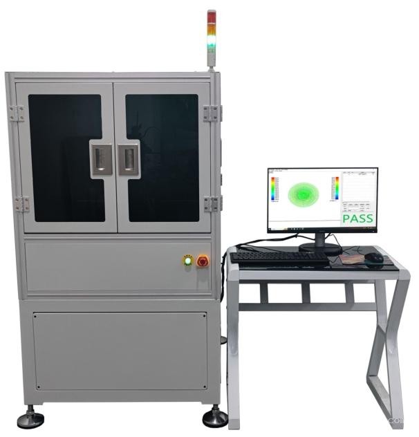
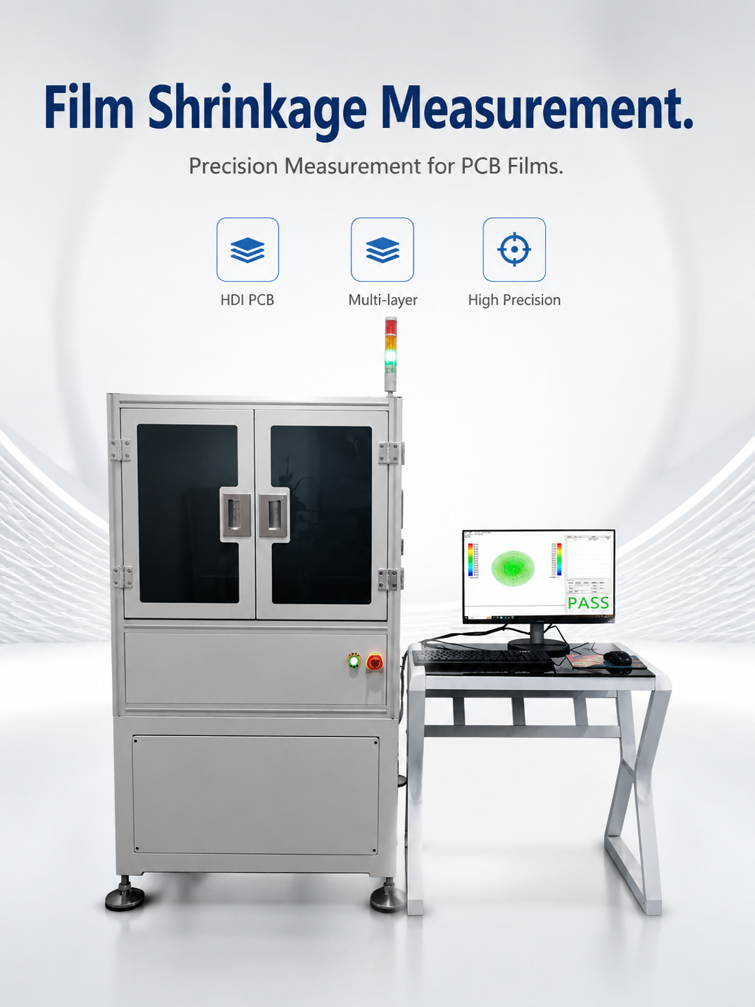
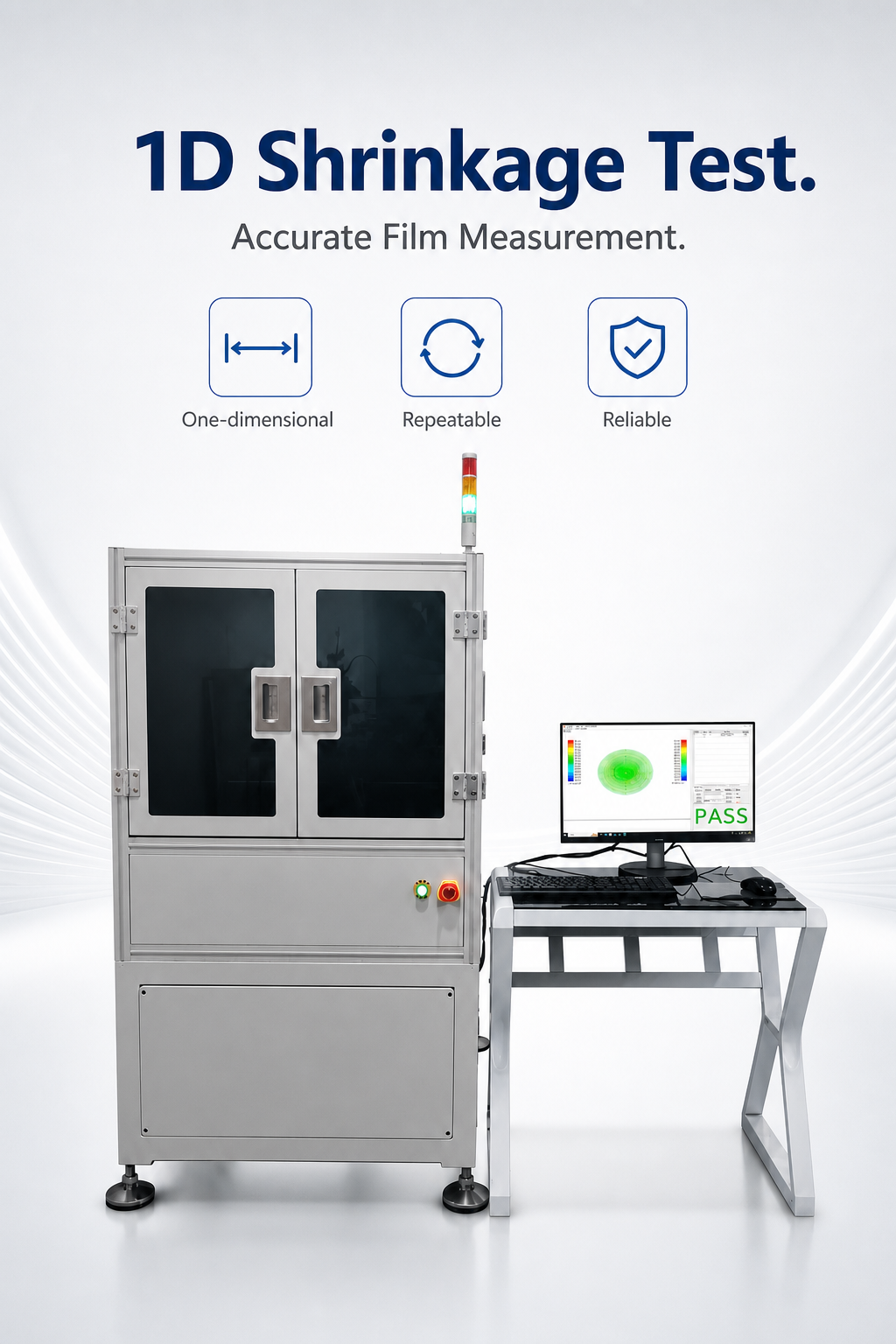
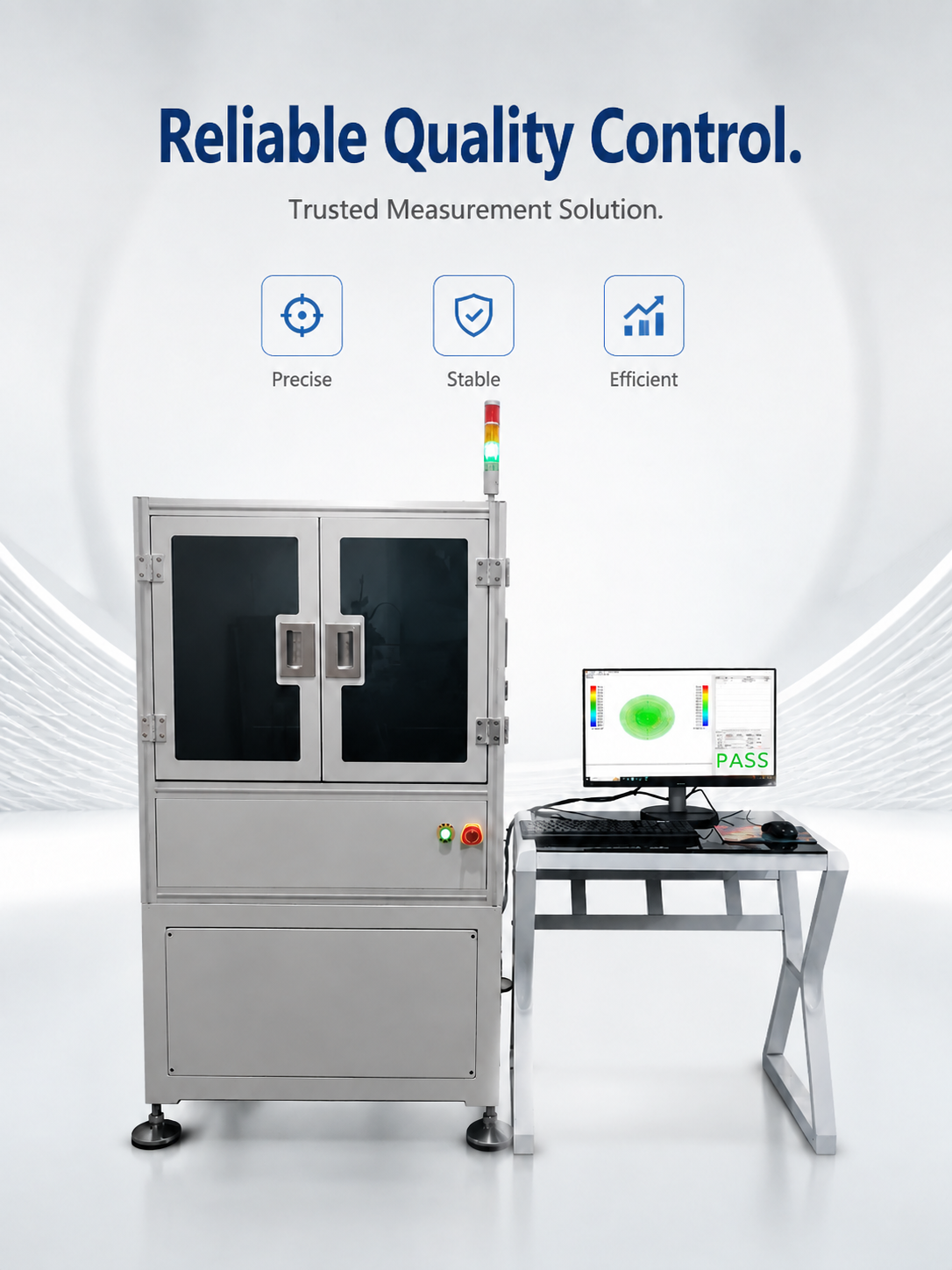
One-dimensional Film Shrinkage Measuring Machine For HDI & Multi-layer PCB

Get real shrinkage numbers on films and core boards, from 260 to 900mm.

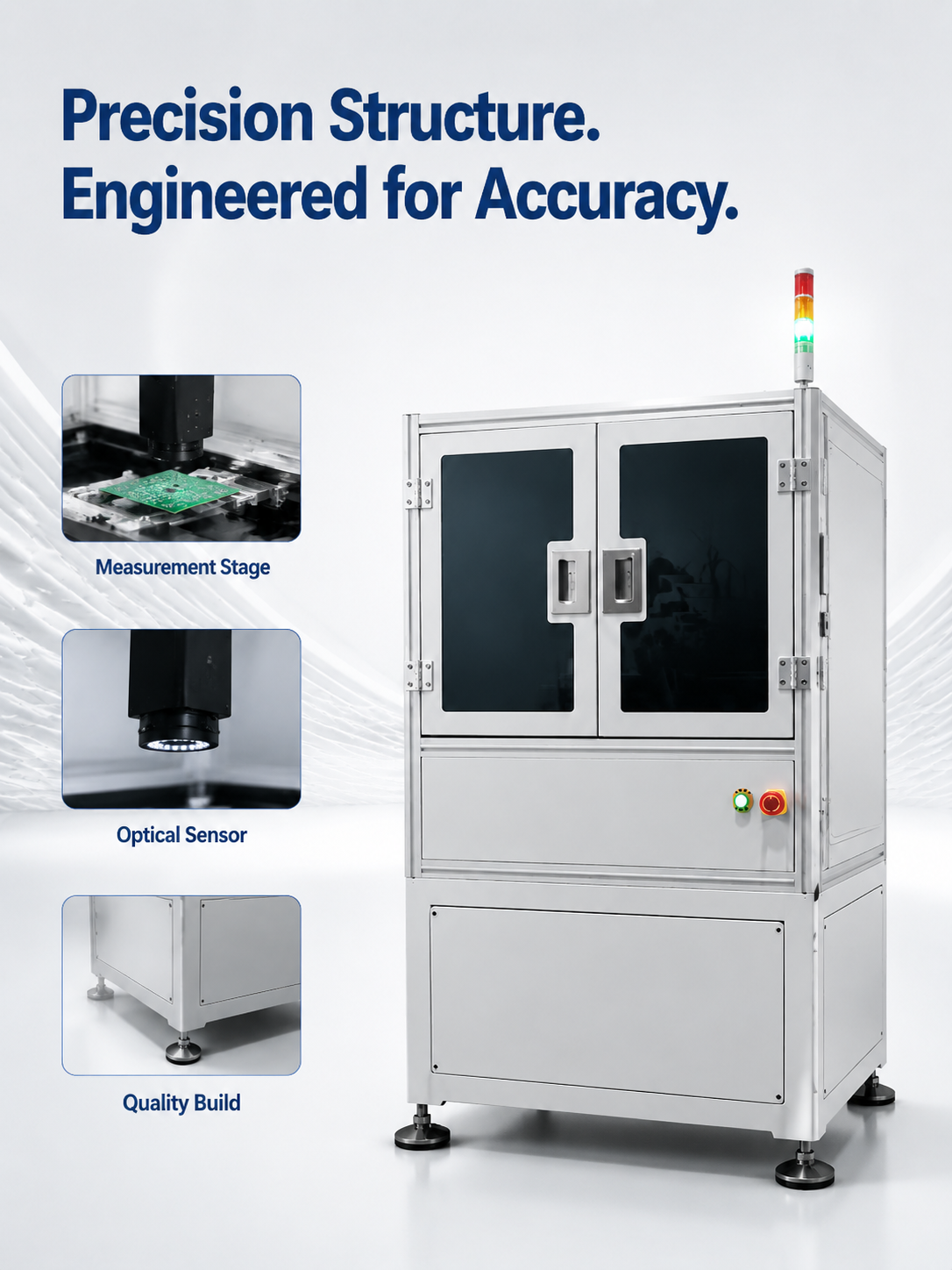
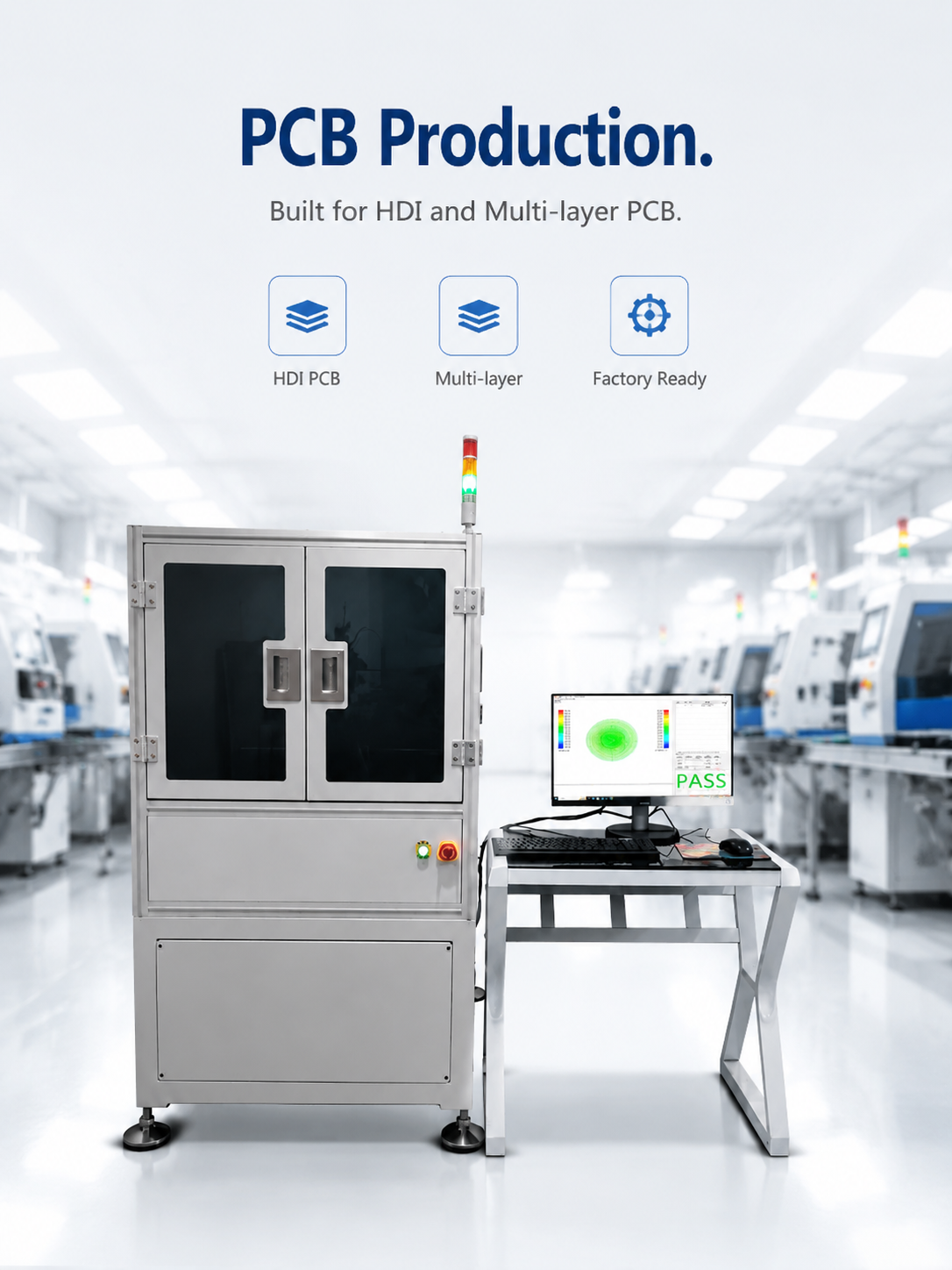
Built for HDI and multi-layer PCB production, this one-dimensional measuring unit checks shrinkage on films, inner core boards, and outer core boards. The patented mask absolute coordinate approach reads a fixed reference to avoid the usual mechanical drift and backlash. You get a solid ±0.156mil max error across a 260–900mm span. That's the kind of data you need when layer-to-layer registration is tight and rework gets expensive.

It's not a universal measuring toy. It's set up specifically for PCB processes, so you can pull compensation factors off real numbers instead of guessing.

One-dimensional Film Shrinkage Measuring Machine For HDI & Multi-layer PCB
#3
Highlights
Key Advantages
  • Uses a fixed mask reference, so you're not chasing thermal drift or lead screw errors every shift.
  • Holds ±0.156mil across the whole 260–900mm range, enough to catch shrinkage before it bites registration.
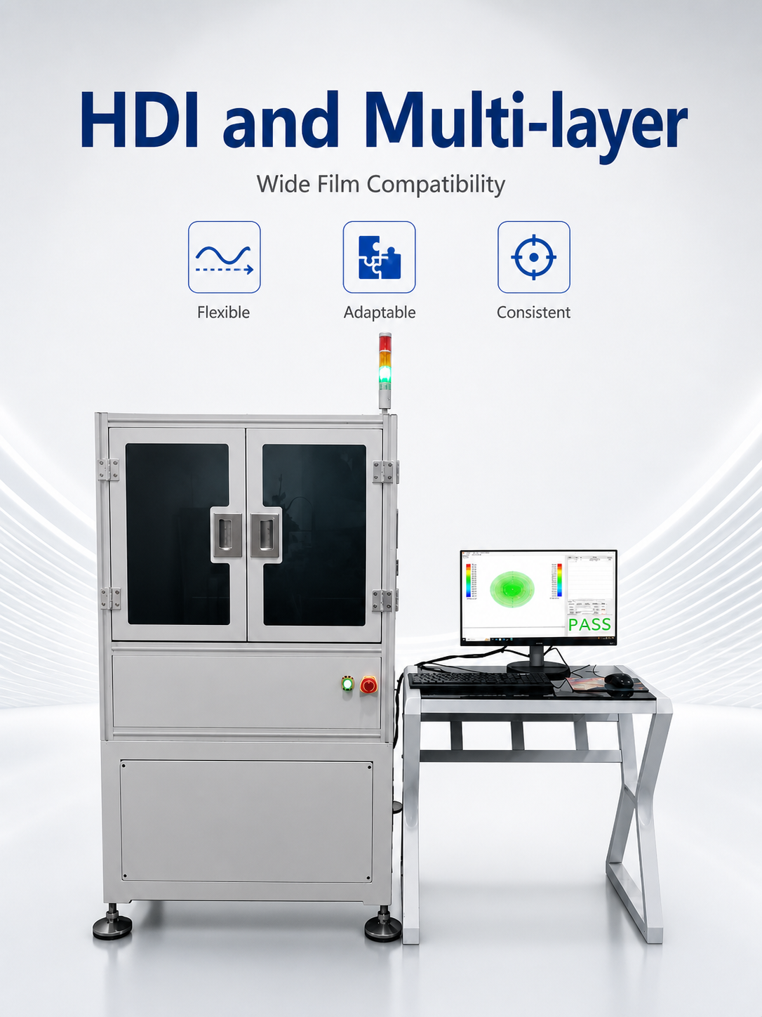
  • Covers films, inner cores, and outer cores in one unit—no need to move parts between three different stations.
  • Set up for HDI and multi-layer boards, not re-purposed from another industry.
  • Gives you the actual shrinkage numbers that feed compensation values, cutting trial-and-error on the line.
Use Cases
Applications
  • Checking film shrinkage before inner layer printing so your artwork actually matches the laminate after processing.
  • Measuring inner core boards after lamination on HDI jobs where via alignment is unforgiving.
  • Inspection of outer core boards before final press to keep layer stackup from wandering.
  • Generating compensation factors for HDI and multi-layer designs, especially on mixed material stacks.
  • Monitoring lot-to-lot material variation from laminate suppliers, so you can adjust before production.
  • Building a dataset for process control on tight registration products like any-layer HDI.
Specs
Technical Specifications
Measuring span260 to 900 mm
Maximum error±0.156 mil (about ±4 µm)
Measuring principleMask absolute coordinate, fixed reference marks
Works onPCB films, inner core boards, outer core boards
Typical materialsFR-4, polyimide, high-Tg laminates, thin core materials
Data outputDigital readout with high resolution and RS-232 export
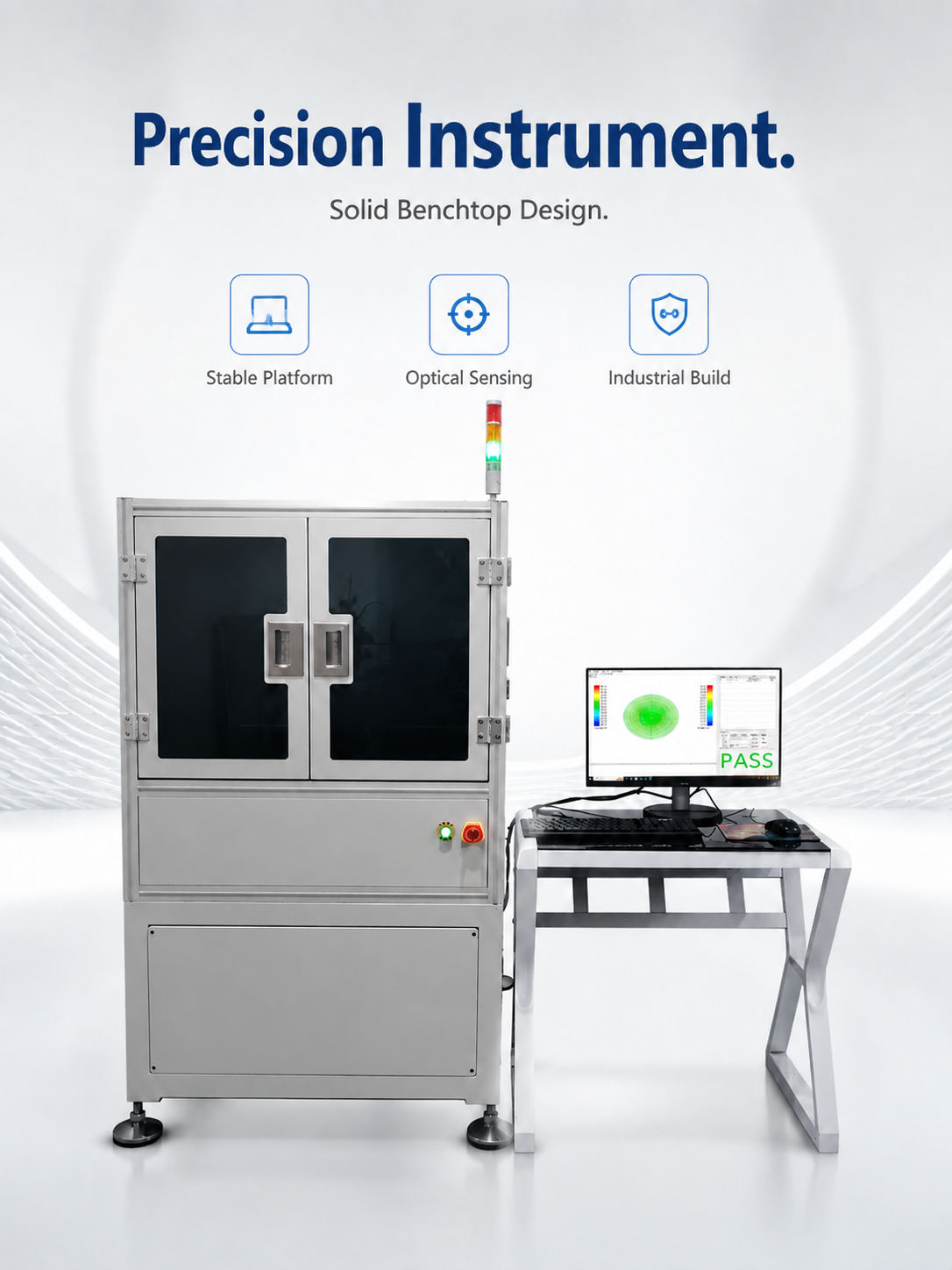
Machine typeOne-dimensional, bench-top
Power110/220 VAC, 50/60 Hz
CustomizationRange extensions, larger stage, custom reference patterns
Details
Detailed Description
Customized for HDI and multi-layer PCB industry, for shrinkage measurement of PCB film, inner & outer core boards. Patented mask absolute coordinate technology eliminates mechanical errors. Measuring range 260–900mm, max accuracy ±0.156mil, essential equipment for PCB dimension deviation control.
FAQ
FAQ
How does the mask absolute coordinate method actually avoid mechanical error?
It reads position against a fixed reference mark on the measurement stage, not accumulated encoder counts. So things like backlash and thermal expansion of the lead screw don't add up over the stroke. That's why the max error stays at ±0.156mil even on a 900mm board.
Can I measure both positive and negative films on this unit?
Yes, as long as the film has the reference marks or you can use a carrier sheet with marks. The machine looks at relative movement between the reference and the feature you're measuring, so film polarity doesn't matter.
What's the real benefit for HDI boards with small annular rings?
HDI boards often have annular rings of 3–4mil. If core shrinkage is off by even 1mil after lamination, you're drilling into the via pad edge. This machine gives you per-lot shrinkage data so you can compensate the drill file and keep the annular ring centered.
Is the ±0.156mil accuracy the same for the full 260–900mm span?
Yes, that's the maximum error over the entire calibrated range. We verify it at multiple points with a traceable standard before shipping, and you can re-check with the included calibration target.
How long does a typical measurement cycle take?
About 15–20 seconds per point. If you measure, say, 9 points on a panel, it's around 3 minutes including setup. That's fast enough for sampling every lot without slowing down production.
What data output options are available?
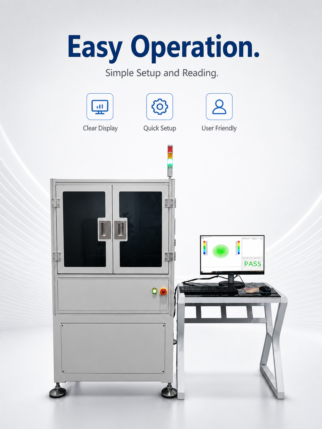
The digital readout shows the shrinkage in mil or µm. You can also export the raw data via RS-232 or USB to a PC for logging and compensation factor calculation in Excel or your SPC software.
Stock
Check Stock & Get a Quote
Send us your panel size and materials. We'll give you a straight answer on how this machine fits your line and what it costs.